On-site service reports
The service report from an assignment to a container vessel is shown below as an example. This gives you an idea of how precisely and meticulously we perform all necessary service work, and how carefully the individual steps are documented for your information upon completion.
Final Report
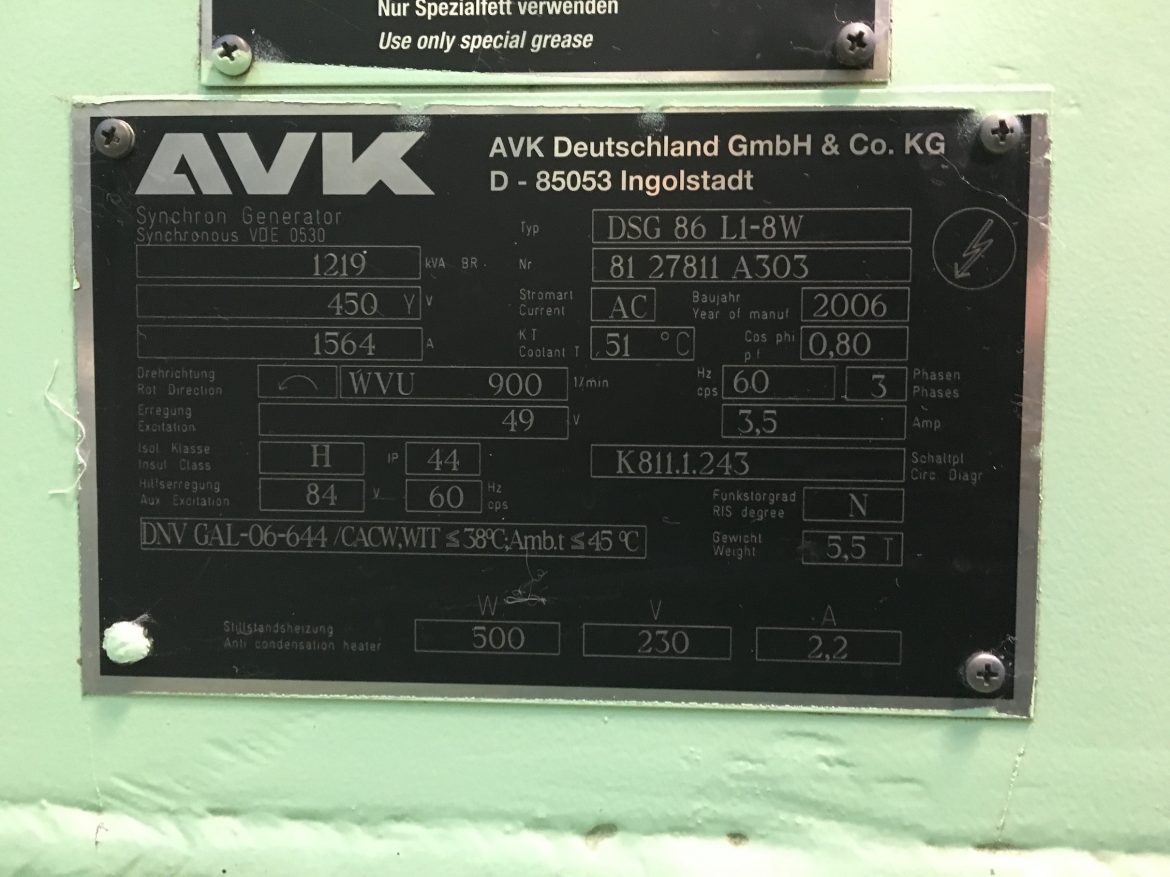
Fabrikat: A.v.K
Type: DSG 86 L1-8WNummer: 8127811 A103
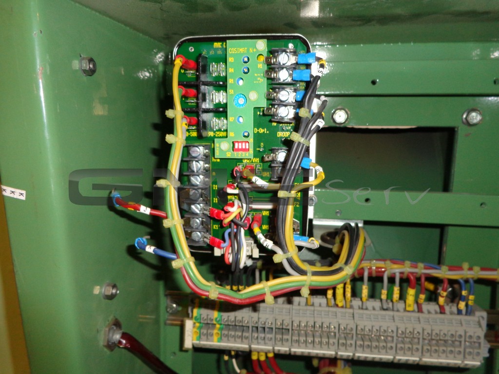
Spg. Regler: Cosimat N+
Leistung: 1219 KVA – 1564 A – 900 U/min – 5500 kg
Error notification from the customer
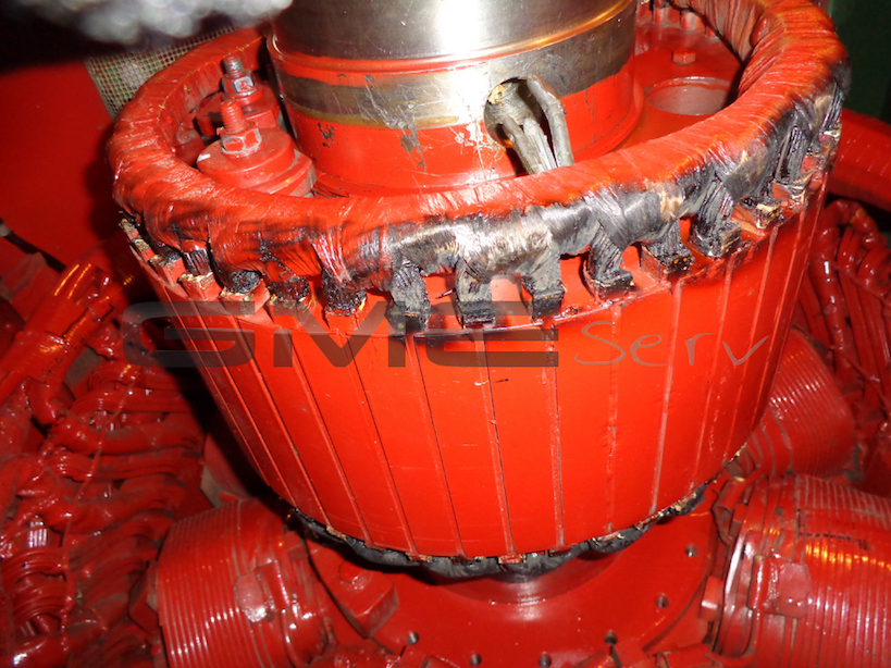
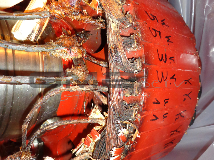
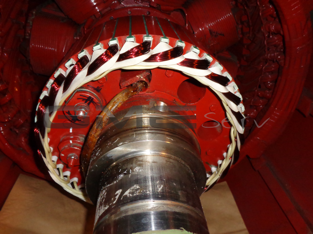
Defective exciter-rotor winding on auxiliary generator from AvK
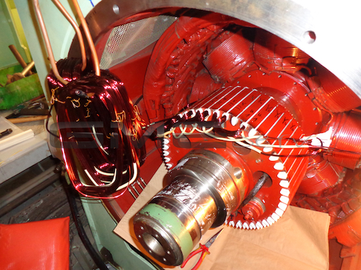
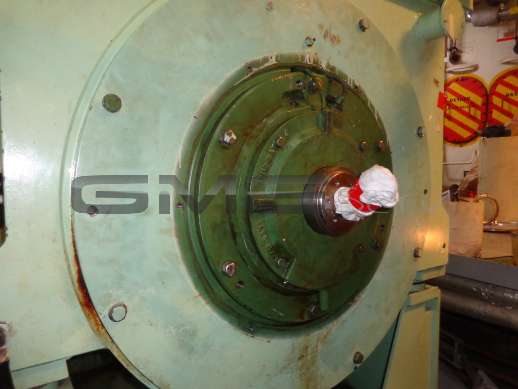
The above-mentioned generator had already been disassembled (by the crew) on the non-drive end when we arrived on board to be able to replace the defective exciter-rotor winding.
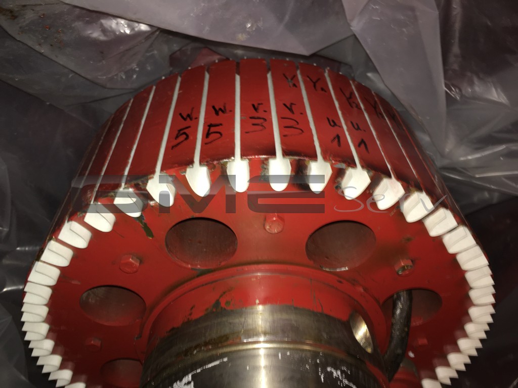
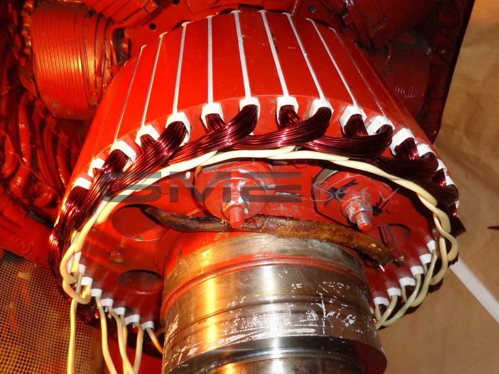
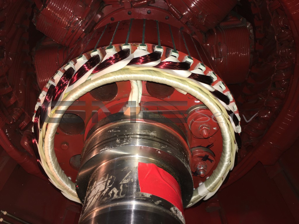
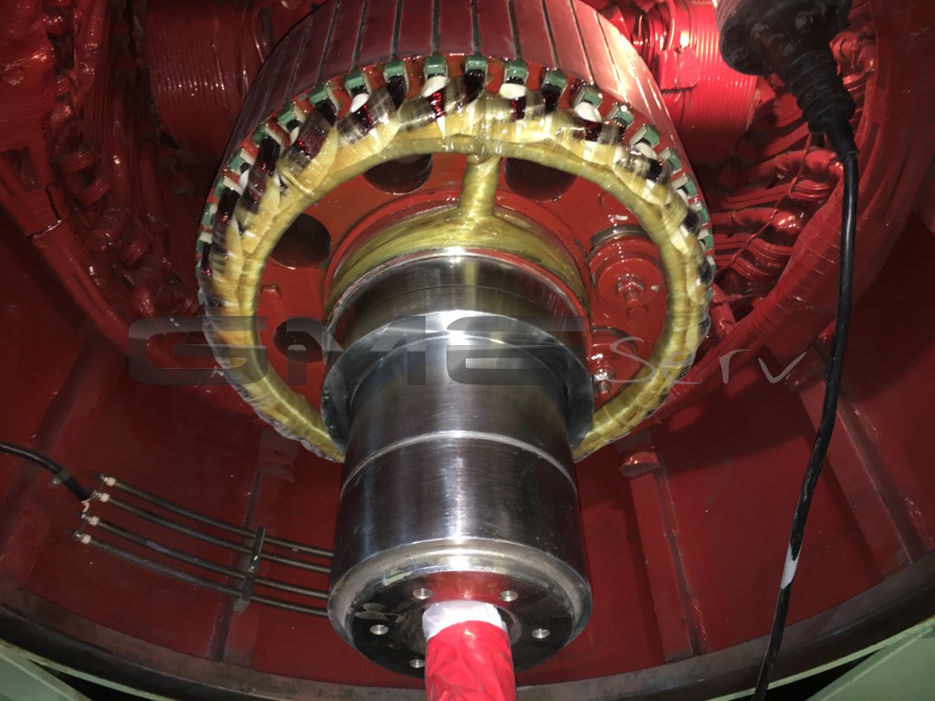
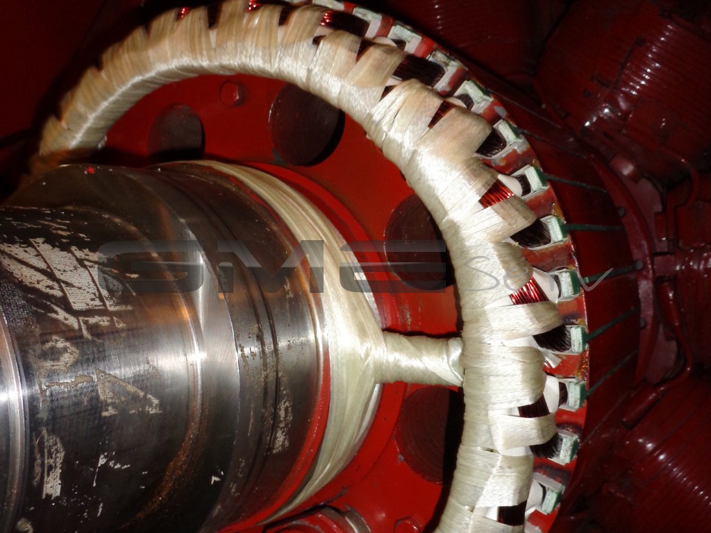
The front winding head was sawn off and removed to be able to hit the individual coil sides through the slots. Subsequently, the slots were cleaned and insulated for the new winding. Then the new winding was inserted, connected, phase-insulated, bandaged and impregnated several times with special cast resin. Subsequently, the individual turns of the winding were checked against each other and against earth using a test voltage of 1,000 V DC and found to be o.k.
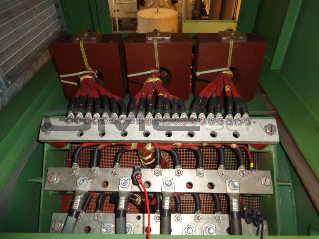
The interconnecting cables between winding and rectifier carrier were routed through an axial bore in the shaft. These cables were removed by the crew and replaced by us.
Subsequently, the cables were checked against each other and earth with 1,000 V DC and found to be o.k.
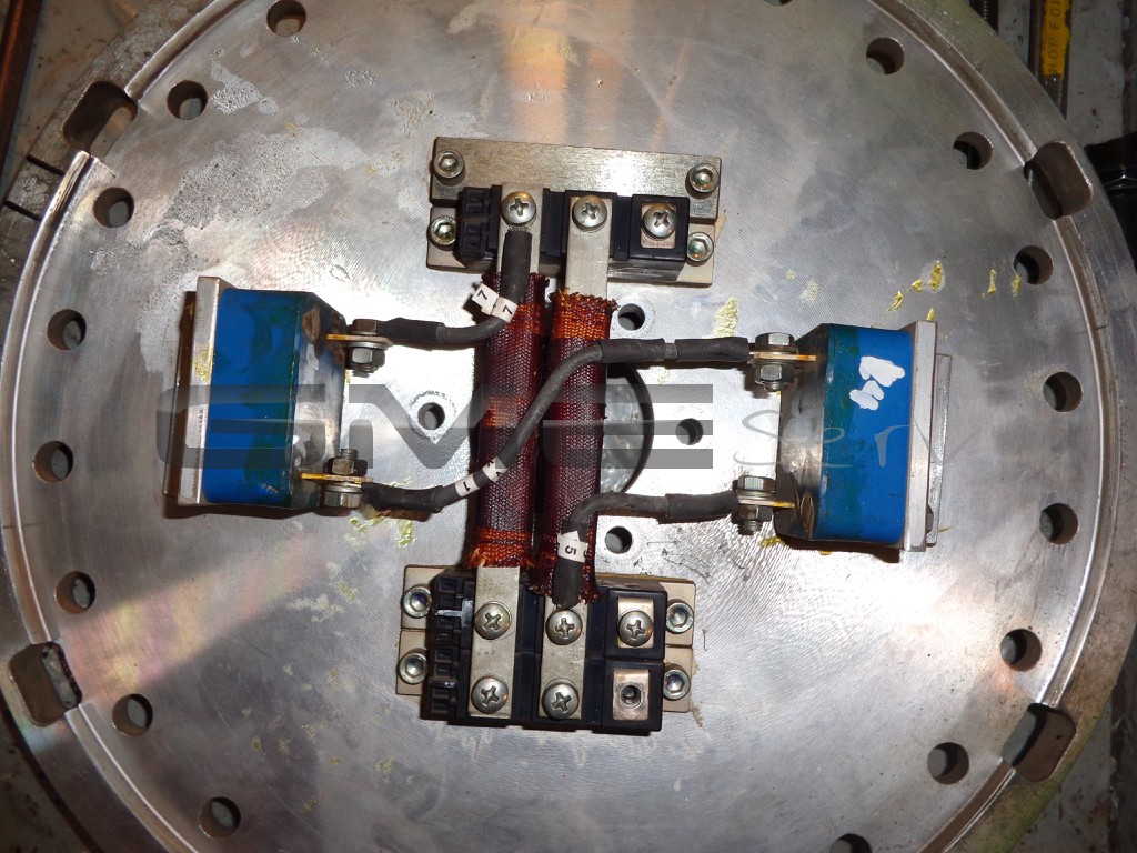
The check of the diodes and varistor also yielded positive results, but for safety reasons, these components were replaced by new ones.
Service report – Vessel – Exciter motor – Motor – GMEServ – Onsite service report
Insulation measurements with 500 VDC were performed on the stator, exciter, auxiliary and main rotor windings;
the insulation resistance was greater than 550 MΩ. The resistances of the individual windings were checked on the basis of the test record and also found to be o.k.
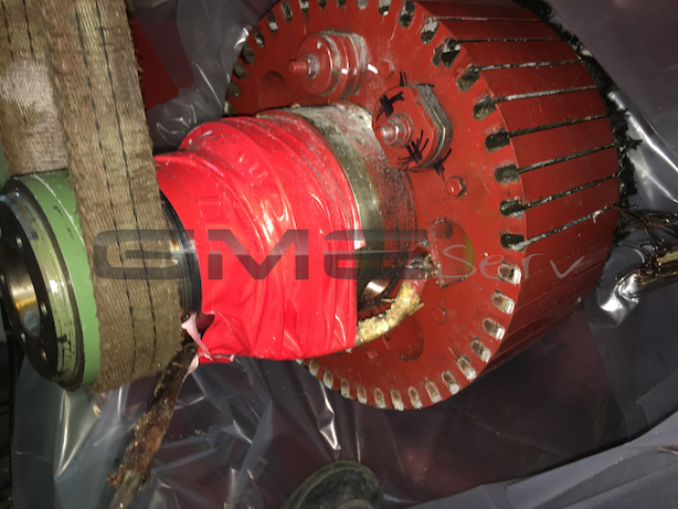
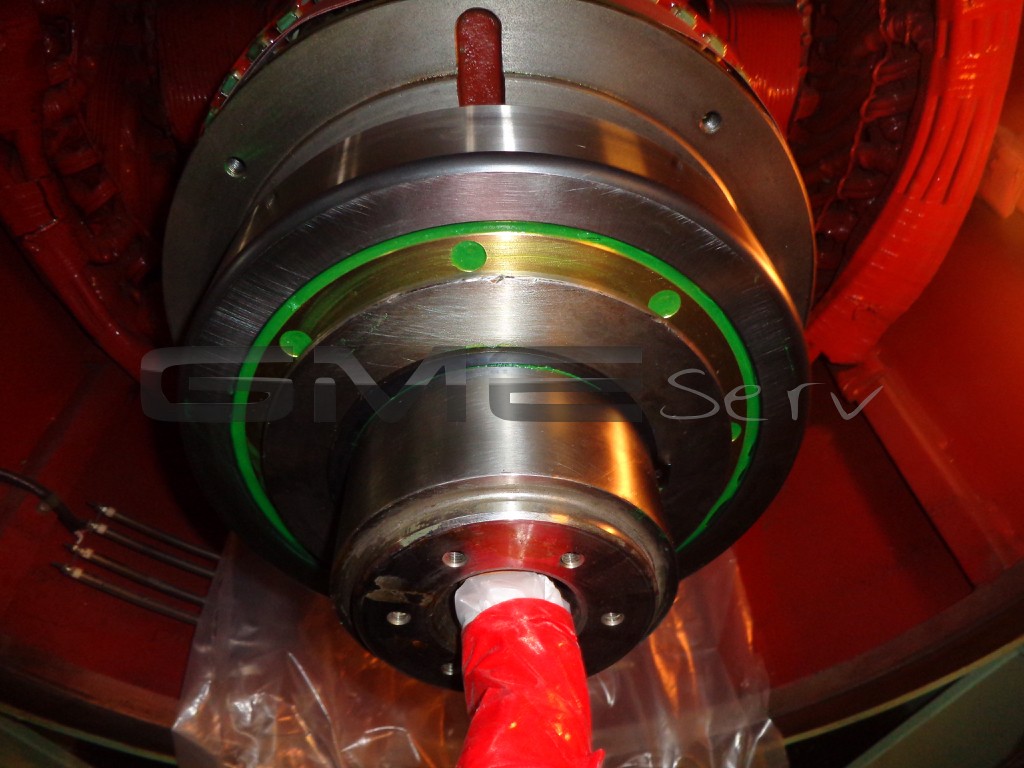
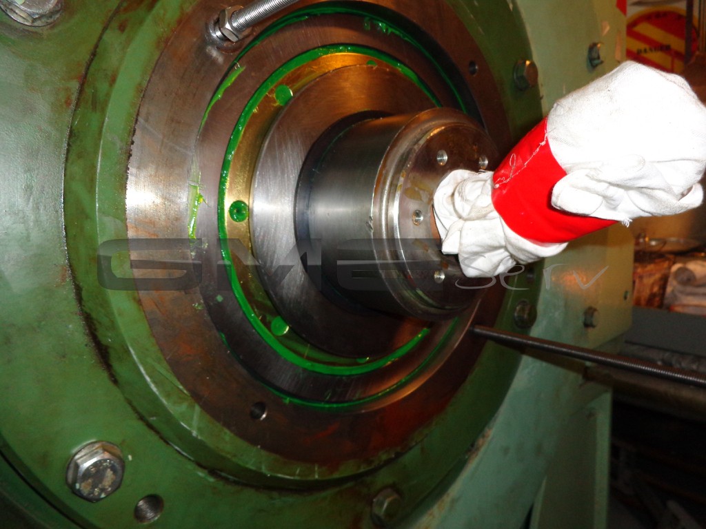
The non-drive-end ball bearing 6328 MC3 was replaced; the bearing seat in the bearing cassette was slightly shrunk (no scoring).
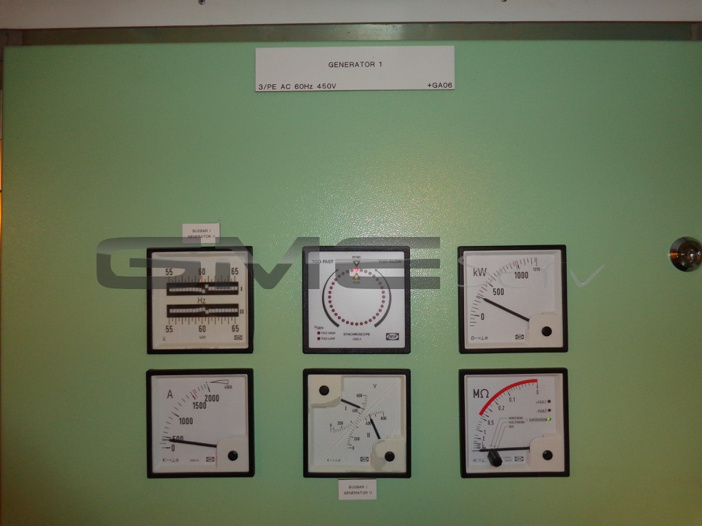
Once the generator has been reassembled completely, it was started for the first time without voltage regulator (residual voltage = 66 VAC). Subsequently, the excitation was provided from an external power source to be able to perform all no-load measurements. The measurement values were compared to the test record and founded to be o.k. During the next step, the new voltage regulator was started up and adjusted. The generator displayed normal operating behaviour both in single and in parallel modes. Finally, the voltage regulators of all 3 generators were readjusted. The final load run was completed to our full satisfaction.
Measuring the resistance of the individual windings as part of the diagnosis:
Main rotor winding I – K : 2.56 Ω
Exciter stator I – K : 11.95 Ω
Auxiliary winding UH1-UH2 : 0.285 Ω
Auxiliary winding WH1-WH2 : 0.290 Ω
All windings were checked against earth using a test voltage of 500 VDC.
Measurement value determined: >550 MΩ
Measuring the resistor of the exciter rotor after rewinding
With star-point connection:
U – V: 0.336 Ω
U – W: 0.337 Ω
V – W: 0.339 Ω
The winding was checked for phase-to-phase fault and against earth using a test voltage of 1,000 VDC.
Measurement values determined:
Check of the winding for phase-to-phase fault : >550 MΩ
Winding against earth : >550 MΩ
Resistance of the anti-condensation heater : 142 Ω
Measurements performed in no-load mode of the generator
Residual voltage on the stator without excitation
With excitation:
Stator voltage U – V – W : 452 V AC
Auxiliary voltage UH1 – UH2 : 85 V AC
Auxiliary voltage WH1 – WH2 : 86 V AC
Exciter stator I – K : 16.1 V DC
Excitation current I – K : 1.4 A DC
Measurements performed with approx. 600 kW and approx. 900 A
Stator voltage U – V – W : 447 V AC
Auxiliary voltage UH1 – UH2 : 87 V AC
Auxiliary voltage WH1 – WH2 : 87 V AC
Exciter stator I – K : 25.7 V DC
Excitation current I – K : 2.1 A DC